
PRODUCT DISCONTINUED: February 2024.
RECOMMENDED SUBSTITUTION: The product has been replaced with a redesigned version of the DCS-100-A v.3 servo driver
DCS-100-A is microcontroller based drive with opto-isolated analog output ±10V. It is used to drive third party servo amplifiers. DCS-100-A is suitable for retrofit of CNC machines which has robust servo power amplifiers for DC motors with analog input.
Drive is based on 16-bit microcontroller with implemented PID control algorithm. As the feedback of DC motor position an incremental encoder with phase-shifted square signal (quadrature encoder) is used. Encoder interface enables 1x, 2x and 4x encoder resolution.
Adjustment of all parameters is performed by using the configuration software ServoTune3.
The input control interface enables control via opto-isolated lines in next modes:
- STEP/DIR/ENABLE,
- CW/CCW/ENABLE,
- Encoder follower in 1x, 2x and 4x decoding, and
- Via analogue input within the range 0÷5 V with and without feedback.
- Built-in soft start function enables DC motor 1s after power on in order to decrease power surge on start.
There is an opto-isolated digital output on drive, named Track Error which is activated if preset value of tracking error offset is exceeded. That output can be used for activation of external circuit for DC motor emergency stop.
Use power supply 8÷24 VDC. Drive has reverse polarity protection.
APPLICATION
- CNC machines retrofit
- Coordinate tables
- Positioning
- Robots
- Education
DRIVE OUTLOOK
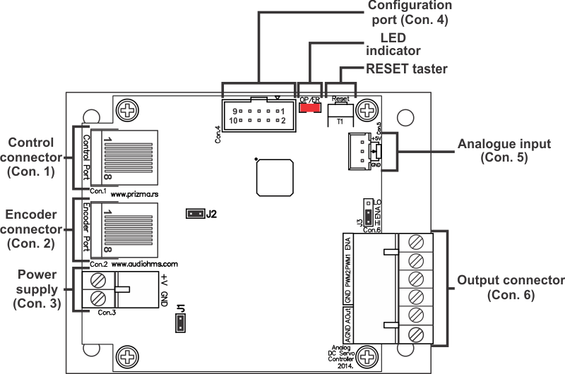
Connector positions on drive DCS-100-A
Image gallery


http://www.audiohms.com/en/cnc-electronics-products/archive-discontinued-products/item/133-dc-servo-drive-with-analogue-output-dcs-100-a#sigProIdcd189600a5
ServoTune3

ServoTune3 is configuration software for DC servo drives.
NOTE: For adjusting parameters od DCS-100-A use software version ServoTune3 Ver.3.09 or later.
![]() ServoTune3 v.3.09 - September 2015.
ServoTune3 v.3.09 - September 2015.
SPECIFICATIONS
| Characteristics | Description |
| Type | Closed loop DC Servo drive with opto-isolated analog output ±10 V and PID control algorithm |
| Number of axis | 1 |
| Input control interface |
Digital control modes via opto-isolated lines STEP/DIR/ENA, CW/CCW/ENA and Encoder follower (1x, 2x and 4x) Analog 0÷5 V with and without feedback |
| Frequency of STEP command | < 600 kHz |
| Command line pulse width | > 0.5 μs |
| Command line current | approx. 10 mA at 5 V |
| Output | Opto-isolated analog ±10V |
| Auxiliary outputs |
Opto-isolated Tracking Error |
| Feedback | Incremental encoder with phase-shifted square signal |
| Incremental encoder resolution | x1, x2 i x4 multiplication, settable by software |
| Incremental encoder power supply | Source on drive +5 V DC / 250 mA |
| Drive parameter set up | Via IDC10 connector and programming interface (IPI-USB or Bluetooth BT-PI) |
| Power supply | 8÷24 VDC, 250 mA – reverse polarity protection |
| Dimensions (W x L x H) | 102 mm x 77 mm x 31 mm |
| Weight | 150 g approx. |
NOTE: Specifications are subject to change without notice